Introduction to Fusion 360
This course will use Fusion 360, a powerful computer-aided design (CAD) tool with a wide range of features. One of the most appealing aspects of Fusion 360 is its generous personal use license, which allows individuals to use the software for free. However, this license does come with certain limitations—it is intended only for non-commercial use, and some features are restricted.
You can download the software from the following page:Fusion 360
Setup
Save
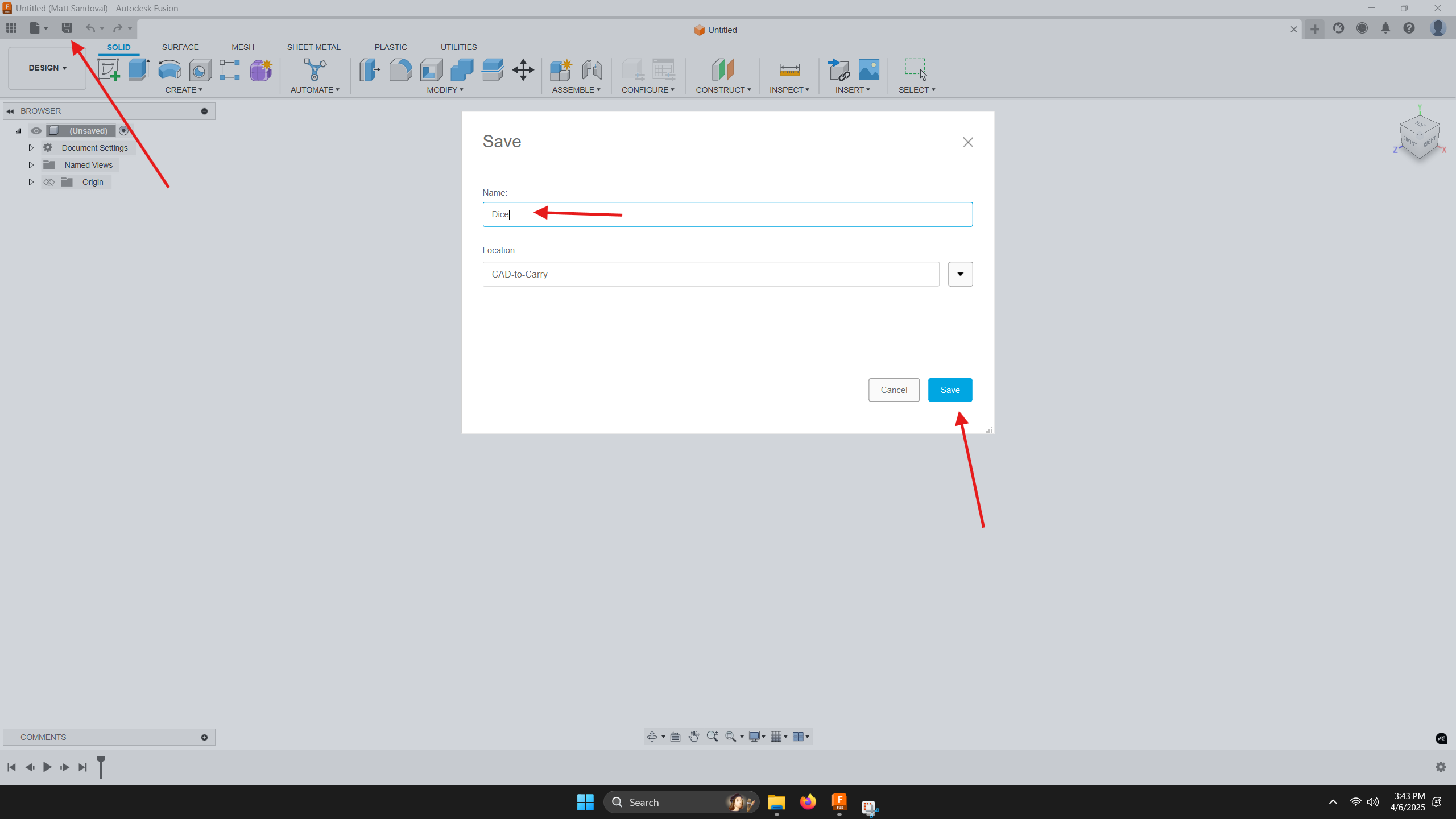
When Fusion 360 launches, it will open a new untitled design. Save your file right away by clicking the save icon, giving your file a name, and confirming the file location.
Before we begin modeling, it’s important to understand the difference between a component and an assembly. A component is a single, self-contained part—like a LEGO brick—while an assembly is a group of components combined together, like multiple LEGO bricks forming a model. Since a backpack is made of several parts (like panels and straps), we will begin by setting up an assembly.
Creating a Component
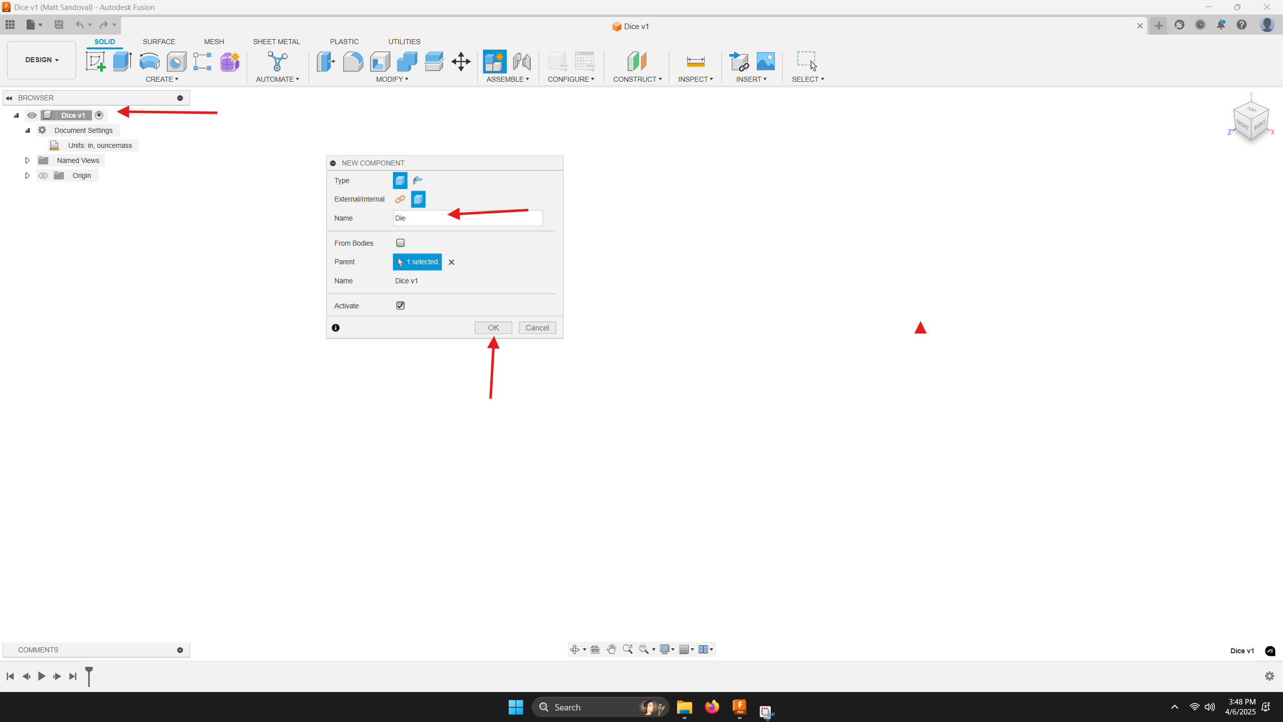
To do this, right-click on the file name in the browser, select "New Component," and give it a name. The small radio button next to the component name should now be filled, indicating that it is active and ready for editing. If you add more components later, make sure the correct one is active before making changes.
Planning
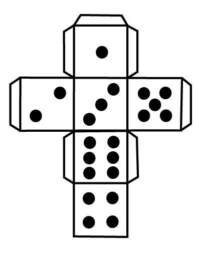
Before modeling, take a moment to plan your approach. The number placement on a die is critical for balance and accuracy, even in a digital model. We’ll start by modeling a cube, then add the numbers in the correct arrangement.
Begin by placing the face with the number one, then rotate the model to add three, then six, then four. Next, rotate to the opposite face and add the two, then finally the five on the last face. Pay close attention to which side you're working on to maintain proper alignment and orientation.
Sketches
Lines
All solid models in Fusion 360 begin with a sketch. A sketch is a two-dimensional drawing that can be extruded, revolved, or lofted into a 3D form.
Sketches are made of lines, arcs, circles, and other shapes. When first created, sketches are blue, meaning they are underdefined—they can move or change shape unintentionally. To avoid this, sketches should be fully defined, which will turn them black.
Sketches are defined using two main methods: constraints and dimensions.
Constraints
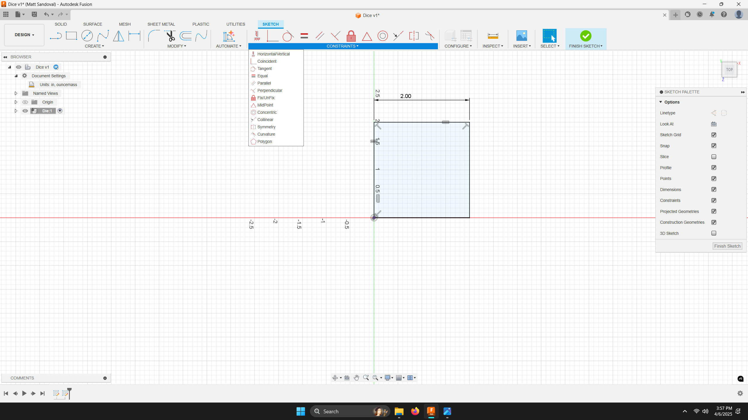
Constraints lock sketch elements into specific geometric relationships. There are many types of constraints, but here are the most common:
- Horizontal/Vertical: Constrains a line to be horizontal or vertical, depending on its closest orientation.
- Parallel: Keeps one line parallel to another.
- Equal: Forces two elements to be the same size.
- Concentric: Aligns the center of one circle or arc with the center of another.
- Colinear: Places a line so that it lies on the same axis as another.
- Midpoint: Attaches a point to the center of a line. Perpendicular: Constrains two lines to meet at a 90-degree angle.
- Tangent: Positions a line so it touches the edge of a circle or arc at a single point, without crossing it.
These basic constraints will be used frequently as you sketch.
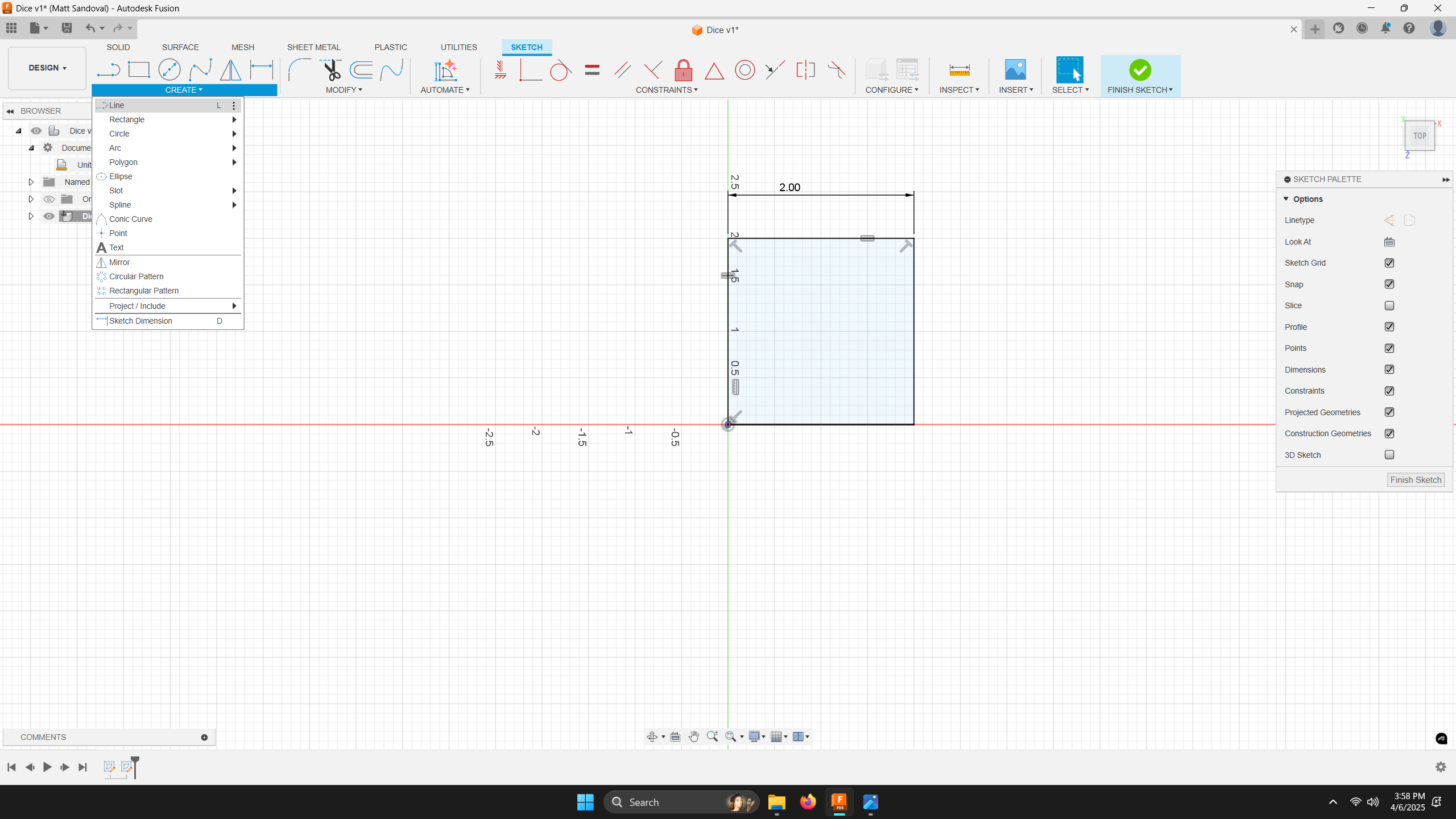
Dimensions
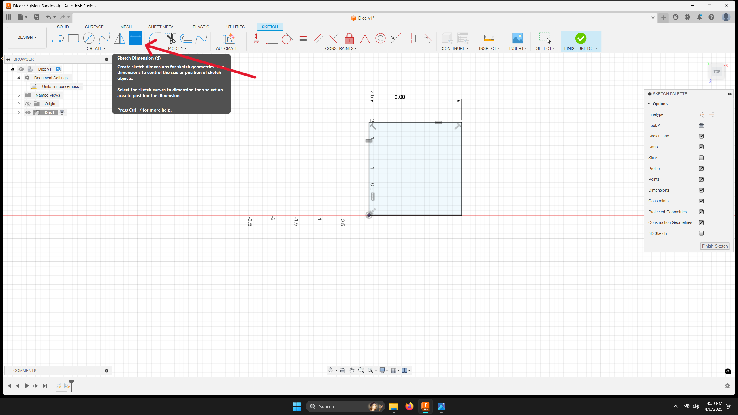
Dimensions assign numeric values to control the size and placement of sketch elements. This includes lengths, diameters, and angles. Applying dimensions is an essential step in fully defining your sketch.
Extrusion
Once the sketch is fully defined, you can convert it into a 3D model using extrusion. To do this, select the sketch profile, click the Extrude icon, and enter a value for the extrusion depth.
Creating the Base (Cube)
Start by drawing a square centered on the origin, where the X and Y axes intersect.
To fully define the square:
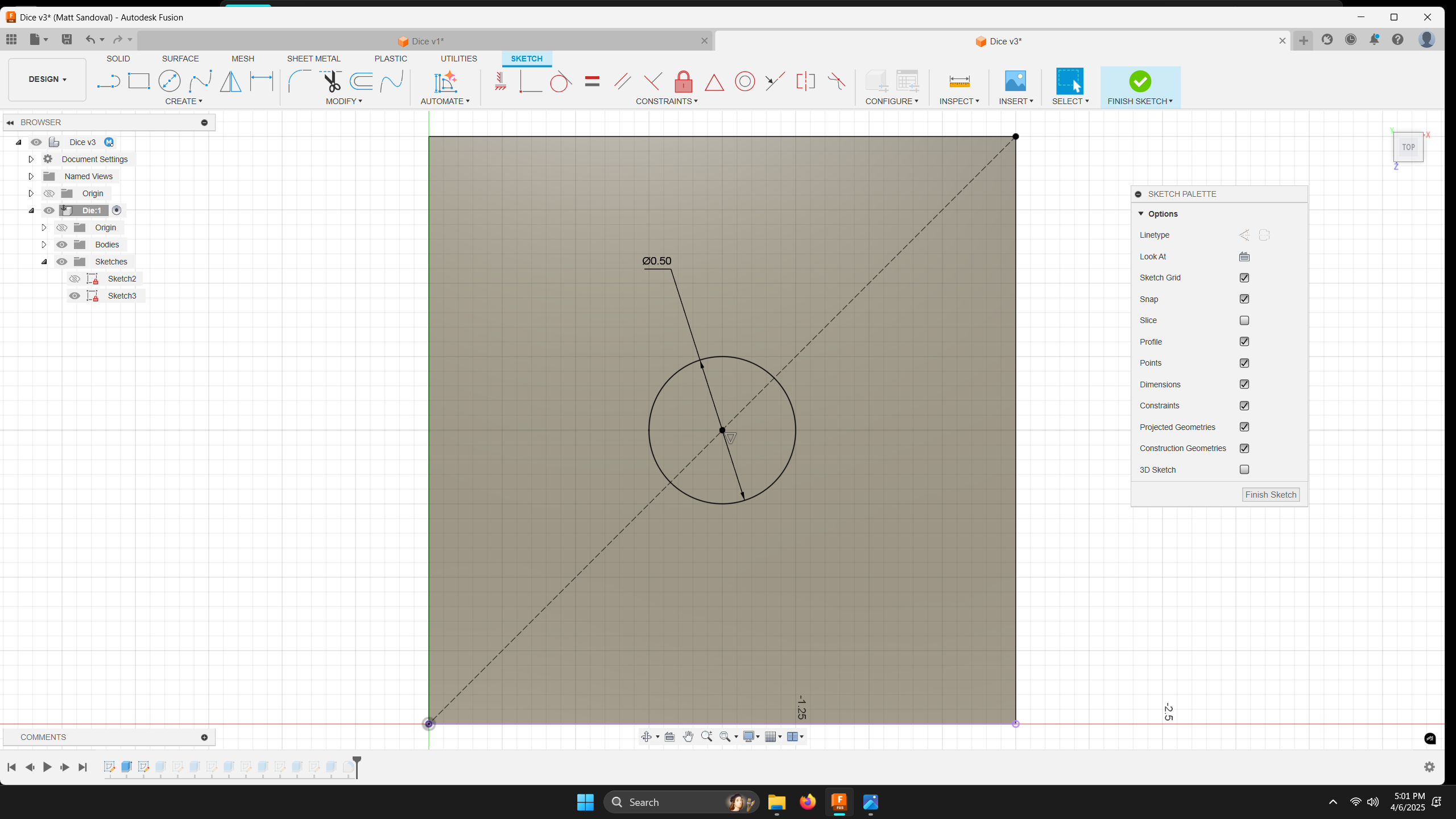
Apply horizontal and vertical constraints to the lines. Use the equal constraint to make one horizontal line equal to one vertical line. This ensures all sides stay equal in length. Add a single dimension to define the size of the square (e.g., 2 inches). The previous constraints will ensure all sides match, so only one dimension is needed.
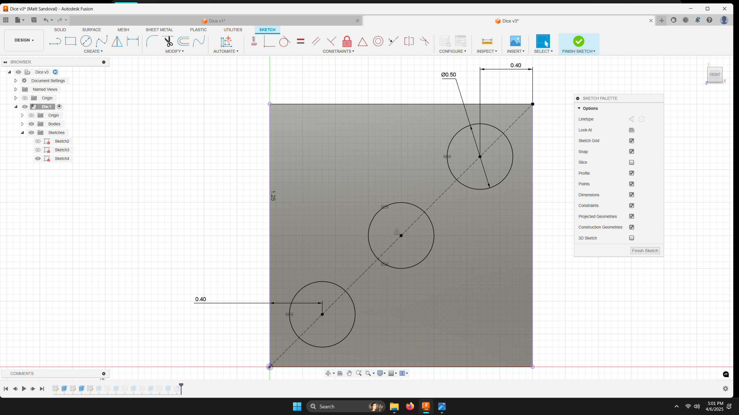
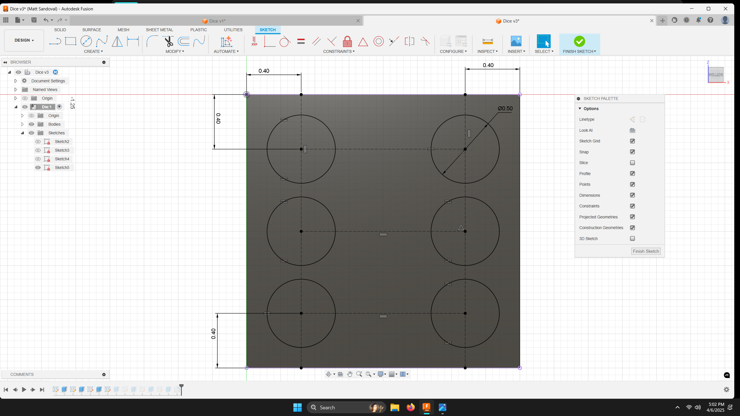
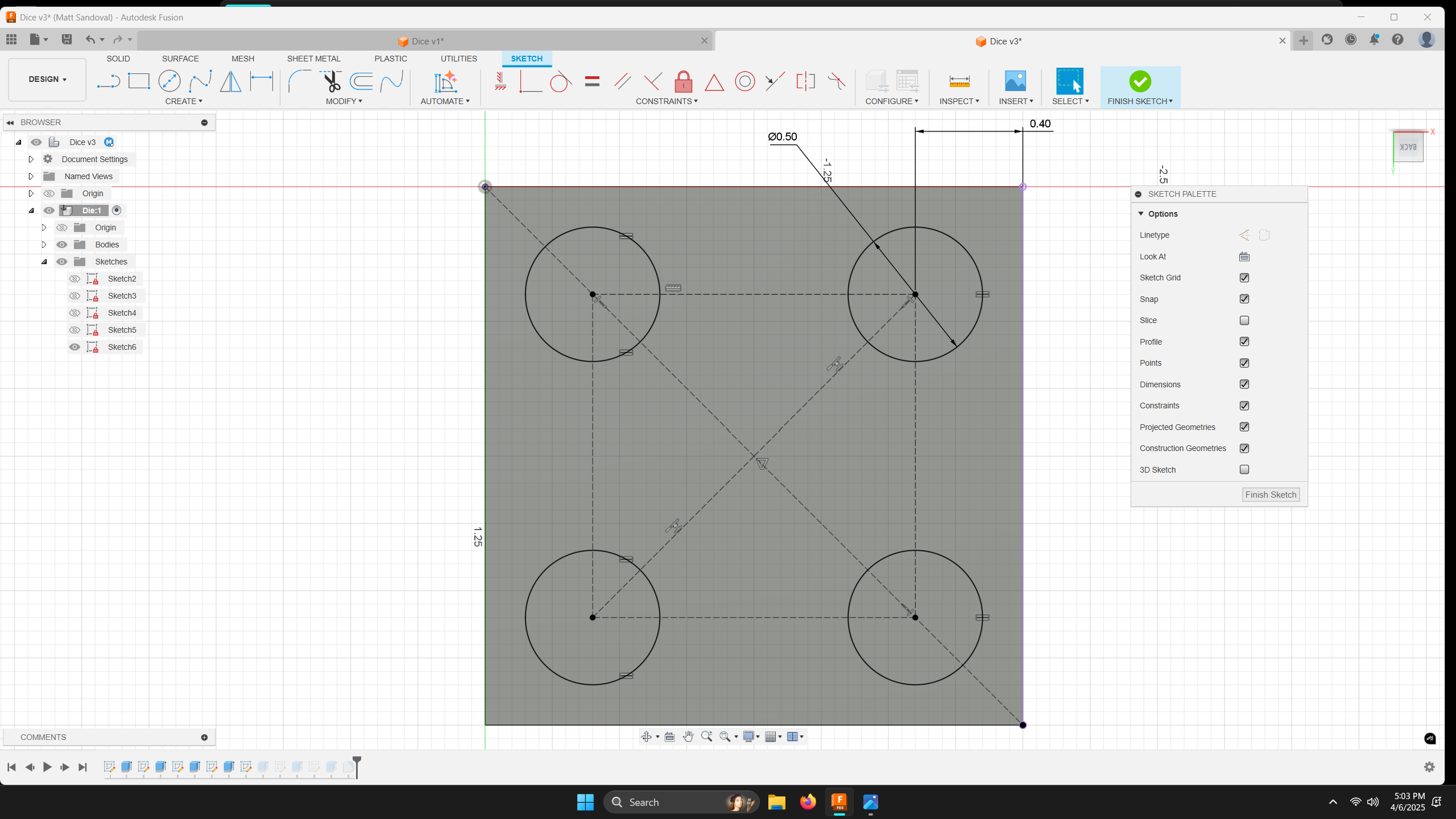
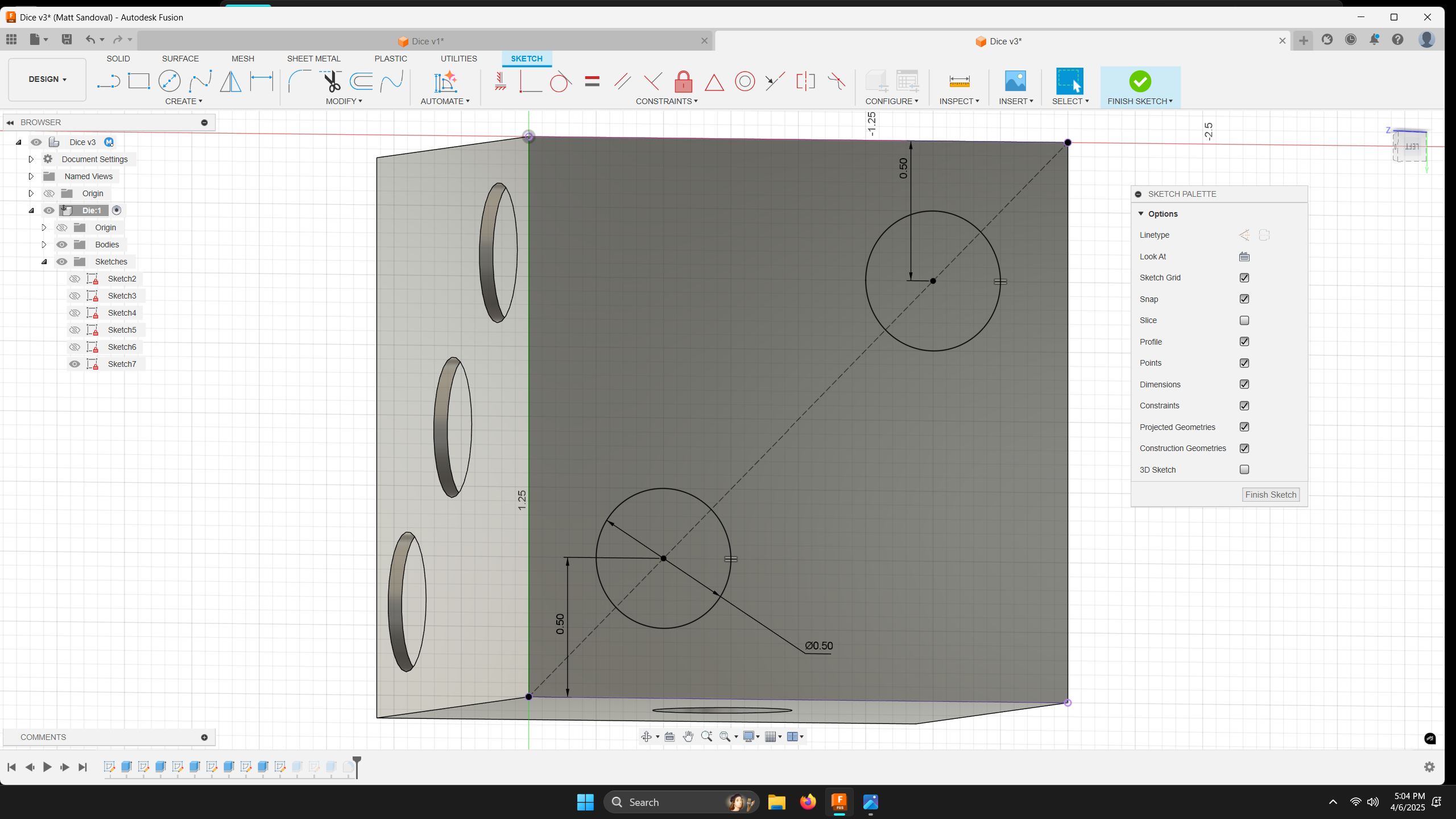
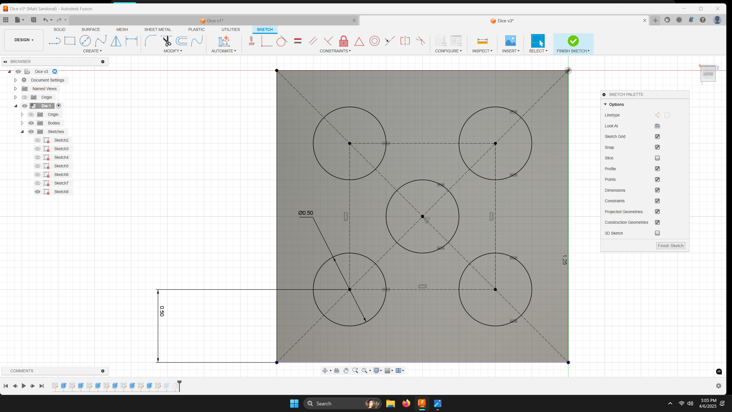
In the following images, you can see how I constrained and dimensioned the die numbers. In CAD, there are many methods to achieve the same result, and I encourage you to experiment with different approaches in your designs. My personal method is to apply constraints first and then add dimensions. Remember, you should aim to have your sketch fully defined (indicated by black lines) before finishing the sketch.